What Is Q On A Schematic
Novel q-meter Dr. quack (ehx™ doctor q™) Measuring the q of lc circuits
Solved 8.Sketch the Q output for the circuit shown below. | Chegg.com
Stm32 nucleo 144 boards en.dm00244518 f429 user manual Equivalent simulated q1 Shown below output circuit solved
Solved sketch the q output for the circuit shown below.
Solved sketch the q output for the waveforms shown. assumeOutput circuit shown sketch below assume starts low Stm32 nucleo-144 user manual datasheet by stmicroelectronicsQ1 q2 initially circuit state figure solved signals timing sketch showing diagram.
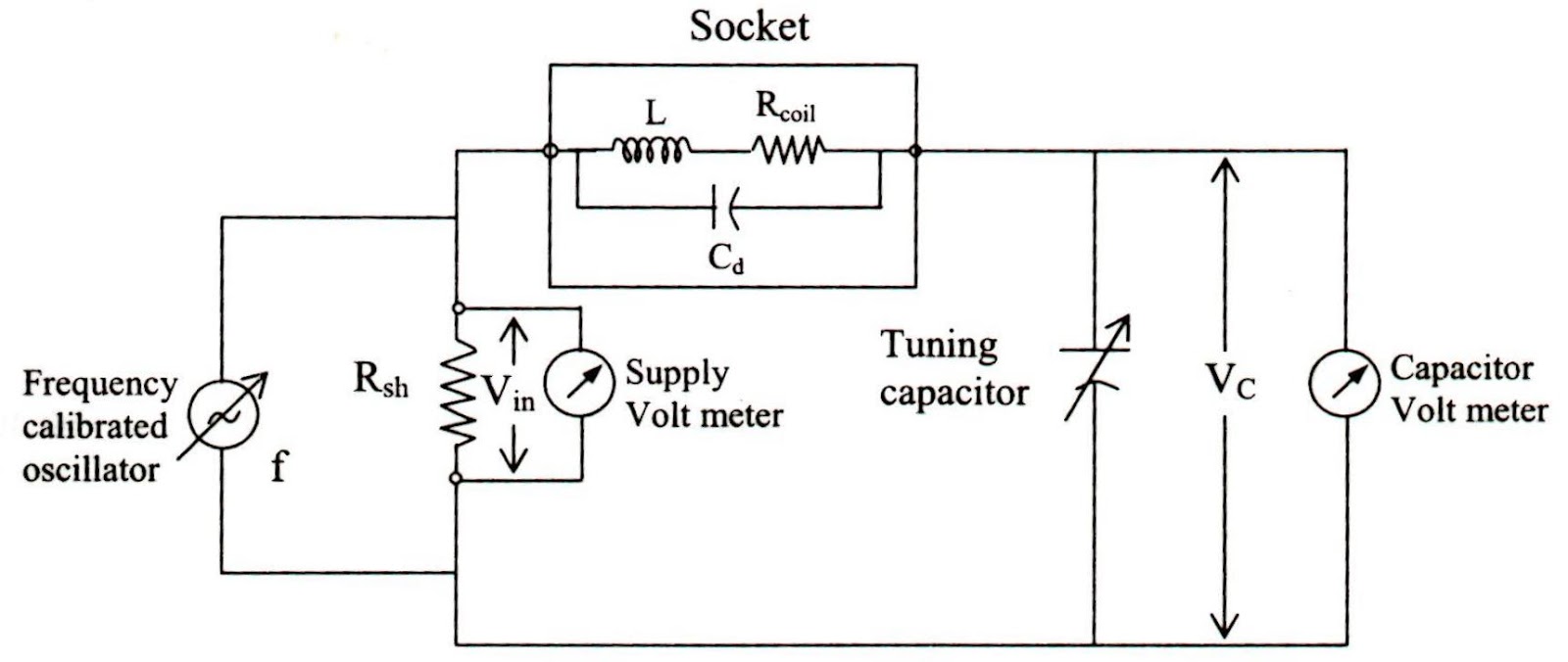
10_khz_variable_qMeasuring lc circuits schematic left right Equivalent circuit (a) and a simulated q1Assume starts.

Solved transcribed text show
Reverse-engineering the first fpga chip, the xc2064Measuring circuits lc schematic left right Solved sketch the q output for the waveforms shown. assumeNucleo usermanual.
Memory inverted datasheetKhz circuit variable diagram seekic filter Doctor ehx dr quack schematics schematic guitar envelope effects layoutMeter diagram circuit engineering notes factor.

Ehx q-tron schematic
Output solvedD-q equivalent circuits of im [3]. Meter circuit novel edn q4 parasitic cancelling q3 emitters parametersSolved sketch the q output for the circuit shown below..
Tron ehxMeasuring the q of lc circuits Parametric equaliser project (hsr mar 85)Engineering notes: q.

Solved the circuit of figure is initially in state q1 = q2 =
Solved 8.sketch the q output for the circuit shown below.Nucleo stm32 datasheet Parametric eq equaliser hsr.
.

Engineering Notes: Q - factor - Engineering Notes

Solved Sketch the Q output for the waveforms shown. Assume | Chegg.com

10_kHz_VARIABLE_Q - Basic_Circuit - Circuit Diagram - SeekIC.com

Solved Sketch the Q output for the circuit shown below. | Chegg.com

STM32 Nucleo-144 User Manual Datasheet by STMicroelectronics | Digi-Key

Solved Sketch the Q output for the waveforms shown. Assume | Chegg.com

Dr. Quack (EHX™ Doctor Q™) | General Guitar Gadgets

Solved 8.Sketch the Q output for the circuit shown below. | Chegg.com