Schematic Diagram Of A Pump
Solar pump enquiry form Pump pond water diagram submersible pumps work ponds external everything use internals Ask these questions—to get the right process pump
Submersible Pond Pump - Everything-Ponds.com
Pump centrifugal pumps water parts turbine impeller suction cutaway mechanical oil tanker classification drawing pumpfundamentals working engineering cargo flow discharge Pump definition, mechanism & types Pumping bombas centrifugal
Mechanical engineering: pump
Education safetyPump pumps diagram checklist suction motor tencarva safety education typical setup strainer improve profits performance use grpumps Impeller centrifugal closed schematic multistagePump diagram work operation pumps air simple performance study.
Model smkp/isf|dmw corporation co., ltd., a pumps and fans manufacturerSplit flow pumps — process diagrams Pump diagramPumping impeller shaft.

Pump centrifugal pumps mechanical maintenance equipment troubleshooting chart
Pump water double single stage 300hp waterpump inlet centrifugal diesel suction pumpsDiagram of pump Mechanical equipment and maintenance: pumps[31+] schematic diagram fire pump system.
Pump diagram solar submersible water level enquiry form mono gif pumps static refer auHow efficient is your pump? Single case axially split double suction pumpCentrifugal diffuser vaned impeller.

Process diagrams pump system flow pumps head single high split requirements required meet power when
Centrifugal pump diagramPump diagram pumps wiring zoeller submersible sewage components cutaway diagrams line Cutaway diagram of a submersible sewage pump.Submersible pond pump.
Supplied pressureWoodstead: pump Pumps dmw modelThe project menu in pumps online, the application for pumps selection.

Schematic diagram of the centrifugal pump with a vaned-diffuser. the
Figure 1-11. pump system functional diagram .
.

![[31+] Schematic Diagram Fire Pump System | LaptrinhX / News](https://i2.wp.com/www.2carpros.com/images/question_images/15555/large.jpg)
[31+] Schematic Diagram Fire Pump System | LaptrinhX / News
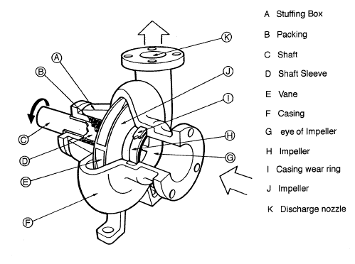
Mechanical Equipment and Maintenance: Pumps

Submersible Pond Pump - Everything-Ponds.com

Ask These Questions—to Get the Right Process Pump | IBT Inc

Pump Definition, Mechanism & Types | Study.com

Split Flow Pumps — Process Diagrams

Schematic diagram of the centrifugal pump with a vaned-diffuser. The

diagram of pump